(1) Balance valve contains a spring, elastic force and spool inertia combined, is a vibration system, in the outside world has a In the outside world there is interference, it is possible to vibrate.
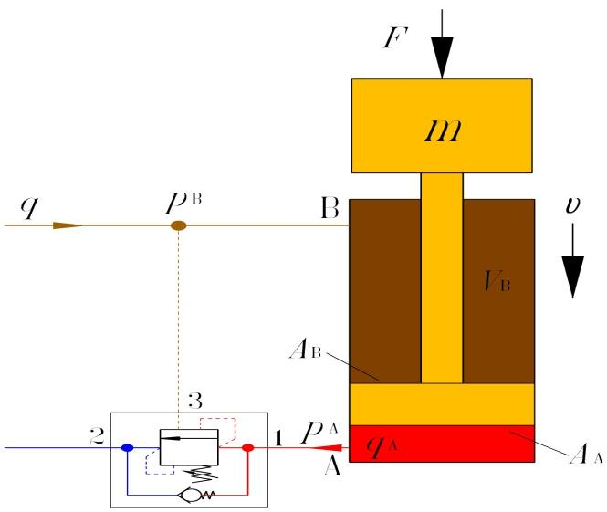
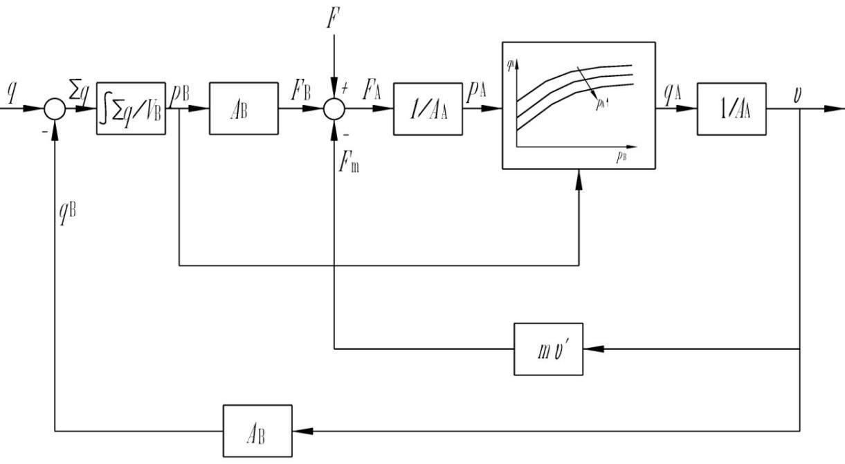
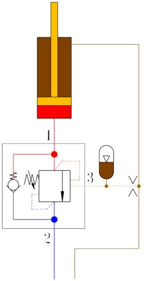
(2) From the point of view of control engineering, the system containing the balancing valve is a closed-loop system, as shown in Figure 19 for a subsystem containing a balancing valve. As shown in Fig. 19, a sub-system with a balancing valve is a closed-loop system. As can be seen from the simplified information flow diagram, the subsystem contains at least two closed-loop valves, even if the effect of velocity v on load F is not taken into account. The subsystem contains at least two closed loops. With closed loops, instability is possible.
a) Hydraulic circuit diagram
b) Simplified information flow diagram
F - external force; FB - force of the upper chamber pressure on the piston;
Fm - load inertia force; FA - vigor applied to the piston
Fig. 19 Subsystem with balancing valve
3) In the system where the balance valve is located, the inertia of some components may be large, such as cranes, lifting platforms, pump trucks, etc. Hydraulic cylinders generally push the load through levers, and the inertia of the load is amplified several times for the hydraulic cylinder. The system usually also contains highly elastic components (liquid capacity, such as accumulators, long hoses, etc.). These inertia and elastic components are combined to form a vibration system.
Because the inertia and elasticity of these components are often not fixed, but constantly change with the movement process. Therefore, the natural frequency is not a few constants, but changes within a wide range. All of these increase the difficulty of control. Therefore, the stability of the system not only depends on the balancing valve, but also is affected by the characteristics of other components in the system.
2. Measures to reduce vibration
(1) Find the cause of the vibration Because of the closed-loop system, once the vibration occurs, the whole system is often vibrating. When the pressure sensor is used to record the pressure change, the pressure at each point is often vibrating, but the amplitude is different. Therefore, it is difficult to determine where the vibration is originating.
One approach is to estimate the frequency of the fundamental wave from the pressure waveform of the pressure sensor. Estimate the natural frequencies of the system and components to determine the source of vibration and try to offset the natural frequencies of the corresponding parts.
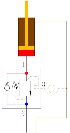
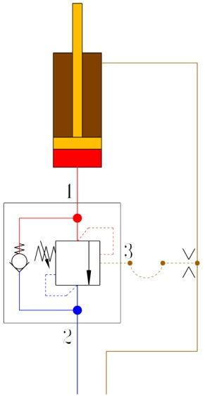
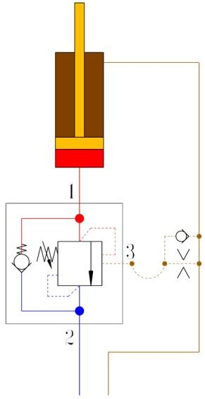
(2) Reduce control pressure fluctuations by increasing the liquid capacity of the control pressure line. (As shown in Figure 20)
A B
C D
Fig. 20 Increasing the fluid volume of the control pressure line
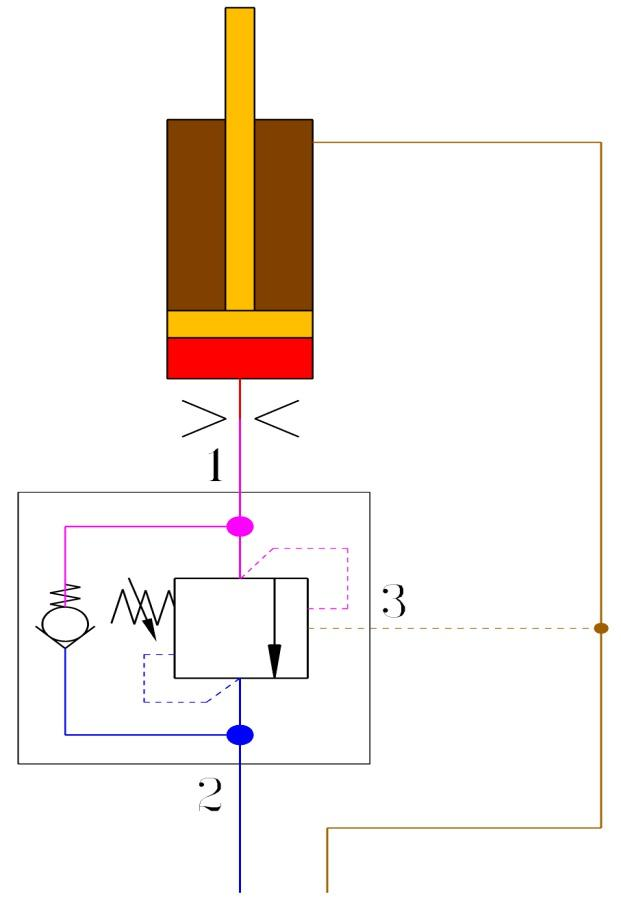
(3) Additional throttling at the load port of the hydraulic cylinder
Adding an appropriate orifice between the hydraulic cylinder load port and the balancing valve, as shown in Figure 21, has several effects.
It can disperse the pressure drop and consume vibration energy.
The pressure drop on both sides of the balance valve throttle is reduced, the throttle will be opened larger, and it will be less sensitive to vibration.
It can be avoided that the poppet valve seat is damaged by impact caused by excessive flow at the moment when the channel is just opened.
However, the simple throttle consumes unnecessary energy when the load increases. Therefore, it is best to use a one-way throttle valve.
(4) Replace other types of balancing valves
(5) Change other software in the system
Some fluctuations may not be completely eliminated by a balancing valve, and improvements must be found elsewhere.
Fig. 21 Distributing the pressure drop with additional throttling
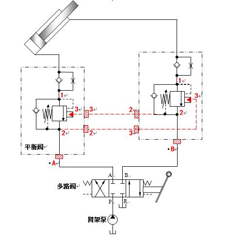
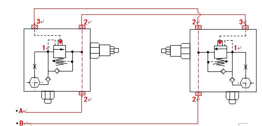
Figure 22 shows the application of a pump truck boom counterbalance valve.


 8616653921805
  sales@sendemach.com
  English